Bestly Gy6 Ac Cdi Wiring Diagram
5 Wire Cdi Wiring Diagram
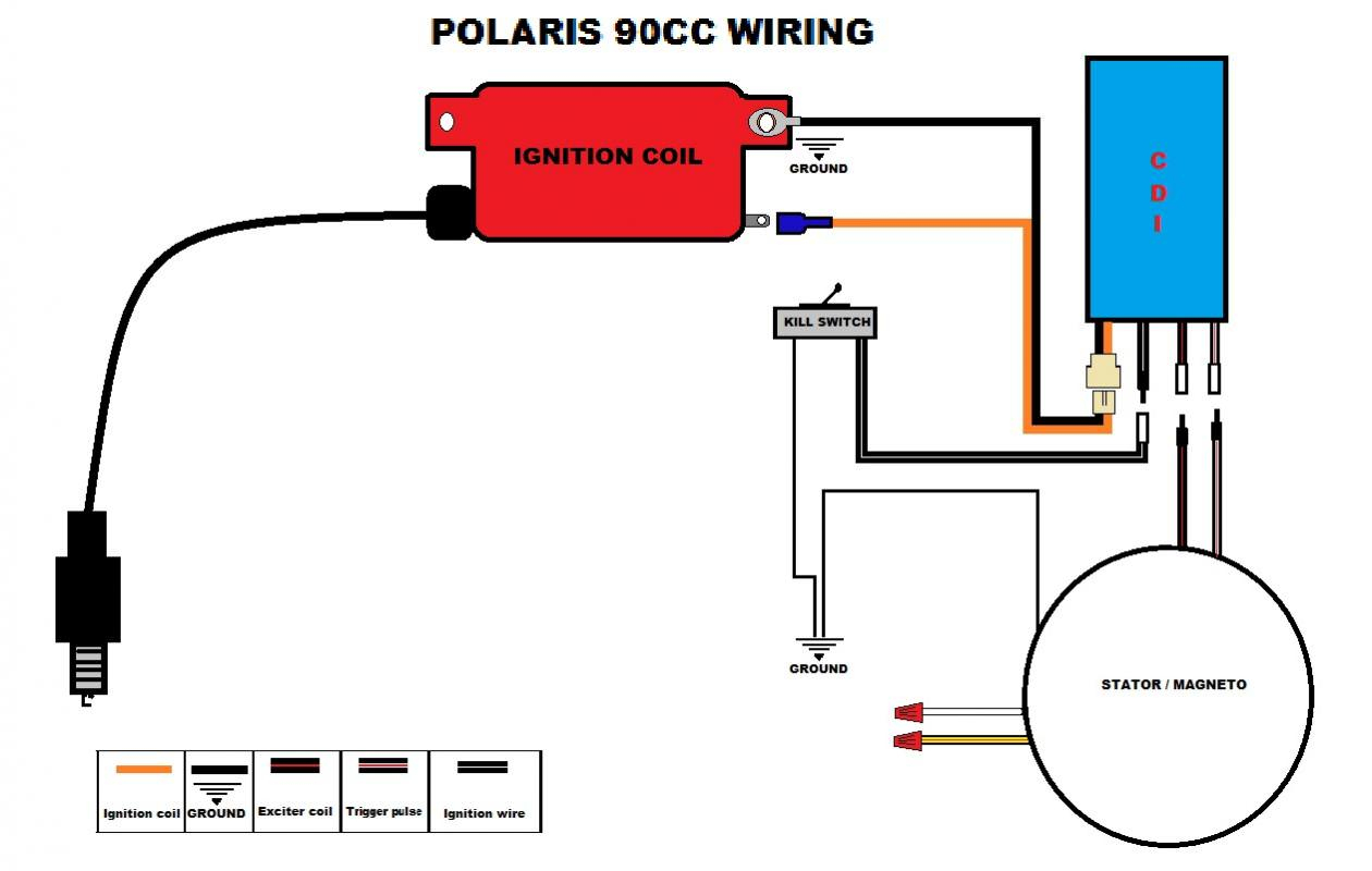
The Polaris CDI wiring diagram provides a clear, visual representation of the vehicle's electrical system. It entails details about the wires, their connection points, and their functions, thereby offering a comprehensive overview of control units, ignition coils, rectifier regulators, and much more.

Racing Cdi Wiring Diagram Collection
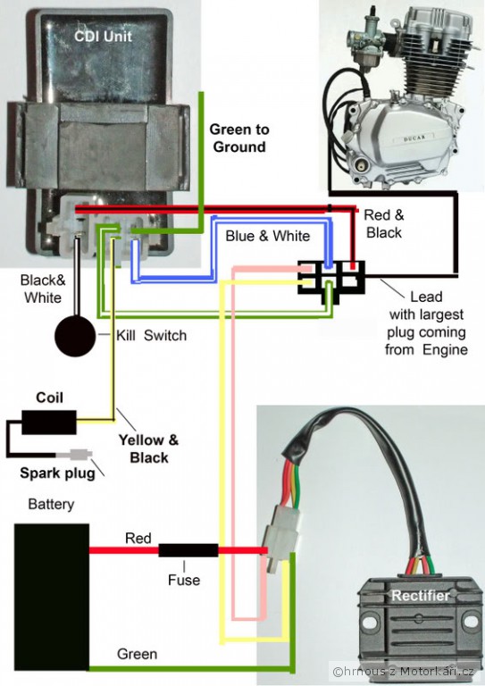
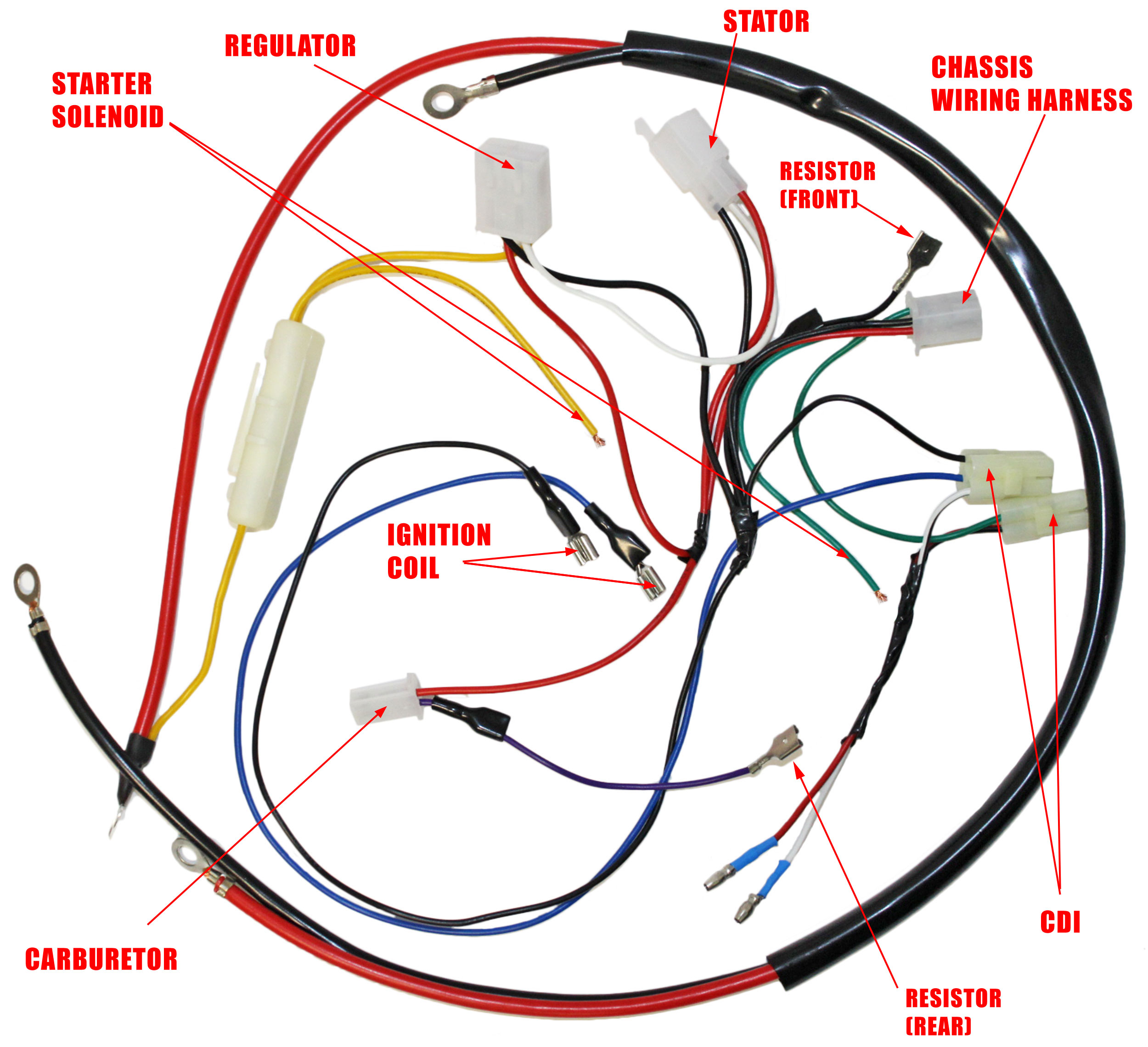
Each wire in the wiring diagram has a specific role, such as connecting the battery, ignition switch, stator coil, and other electrical components. It is important to identify and connect the wires correctly to prevent any electrical shorts or malfunctions. In conclusion, Gy6 DC CDI wiring is a vital aspect of any motorcycle's electrical system.
How To Wire A Cdi
Overhead wiring (OHW) is used to transmit power from traction substations to electric trains. OHW generally consists of catenary and contact wires. The contact wire provides a mechanically continuous path for train pantographs and the catenary wire is used to support the contact wire.

Kymco Cdi Wiring Diagram Wiring Diagram Schematic
Monitoring the burden of CDI in Australian public hospitals The Commission has monitored the national burden of Clostridioides difficile infection (CDI) in Australian public hospitals since 2016. This work has led to a better understanding of CDI acquisition in hospitals and in the community and has helped to inform the development of measures to prevent and limit its spread.
6 pin cdi box wiring diagram
The CDI (Capacitor Discharge Ignition) system is a vital component in the operation of many small engines, including motorcycles, ATVs, and scooters. With the right wiring connections, the CDI box controls the ignition timing, spark intensity, and overall engine performance.

6 Pin CDI Wiring Diagram (Illustrated AND Explained!) OffRoad Official
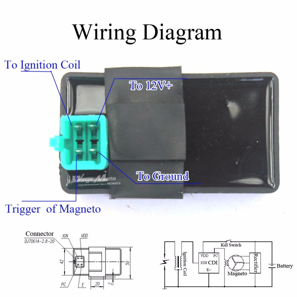
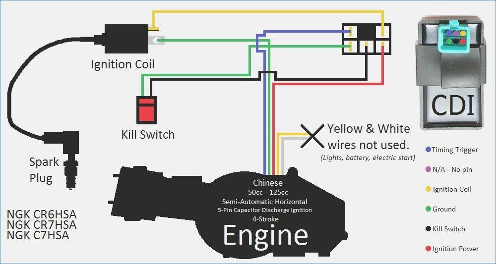
The 5-Pin CDI Wiring Diagram Explained. A 5-pin CDI (Capacitor Discharge Ignition) unit is an important component in the ignition system of many small engines, including motorcycles, dirt bikes, and ATVs. It is responsible for generating the high-voltage spark that ignites the fuel-air mixture in the engine's combustion chamber. Understanding.

8 Pin Cdi Wiring Diagram Collection
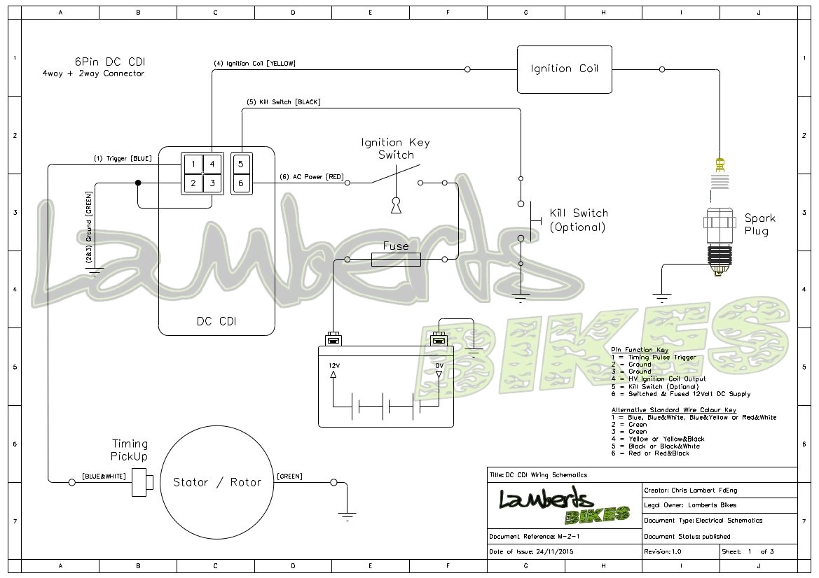
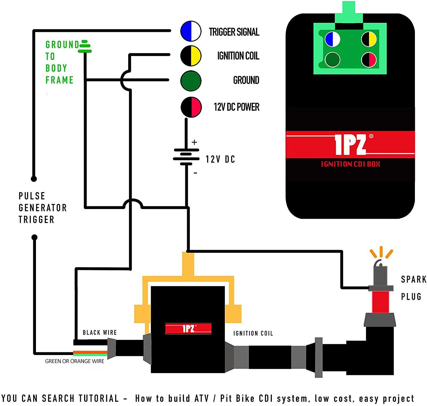
How a CDI Works III. The 5 Pin CDI Box IV. Connecting The 5 Pin CDI Box - Timing Trigger - Ignition Coil - Kill Switch or Key Switch - CDI Ignition Power - Ground VI. 5 Pin CDI Wiring Diagram - AC CDI Box or DC CDI Box? - AC CDI Box - DC CDI Box VII. Conclusion What Is A CDI System?
Gy6 150cc Cdi Wiring Diagram Wiring Harness Diagram
The good news is that by learning how CDI systems work and using the correct 5 pin CDI wiring diagram for your particular model, you can diagnose and fix ignition issues on your own and get your wheels back on the road. In this complete guide, you'll learn: How 5 pin CDI ignition systems work The purpose of each wire in a CDI wiring harness

Cdi Ignition Wiring Diagram Herbalic
The 5 pin CDI wiring diagram is a crucial tool for automotive repair professionals. It provides vital information about the internal workings of a car's electronic ignition system. This diagram is typically used to troubleshoot issues with a vehicle's engine performance, such as a shorted spark plug wire. With a 5 pin CDI wiring diagram.
Cdi Wiring Diagram Wiring Diagram
The CDI system (Capacitor Discharge Ignition) is an electronic ignition device used in a wide range of vehicles powered by smaller engines. It is the most important part of the ignition system for many scooters, go karts, motorcycles, ATVs, quads, and lawnmowers.
2 Stroke Cdi Wiring Diagram
By grasping the significance of each wire connection, this wiring diagram empowers you to troubleshoot issues, make necessary repairs, or even upgrade your CDI box with ease. Equipped with this understanding, you'll embark on exciting motorcycle adventures with peace of mind.

Understanding 110Cc 5 Pin Cdi Wiring Diagram WIREGRAM
A Capacitor Discharge System, commonly referred to as CDI, is an electronic ignition device used in a number of different vehicles powered by smaller engines including ATVs, UTVs, Go-Karts, motorcycles, dirt bikes, scooters and lawnmowers.
Bestly Gy6 Ac Cdi Wiring Diagram
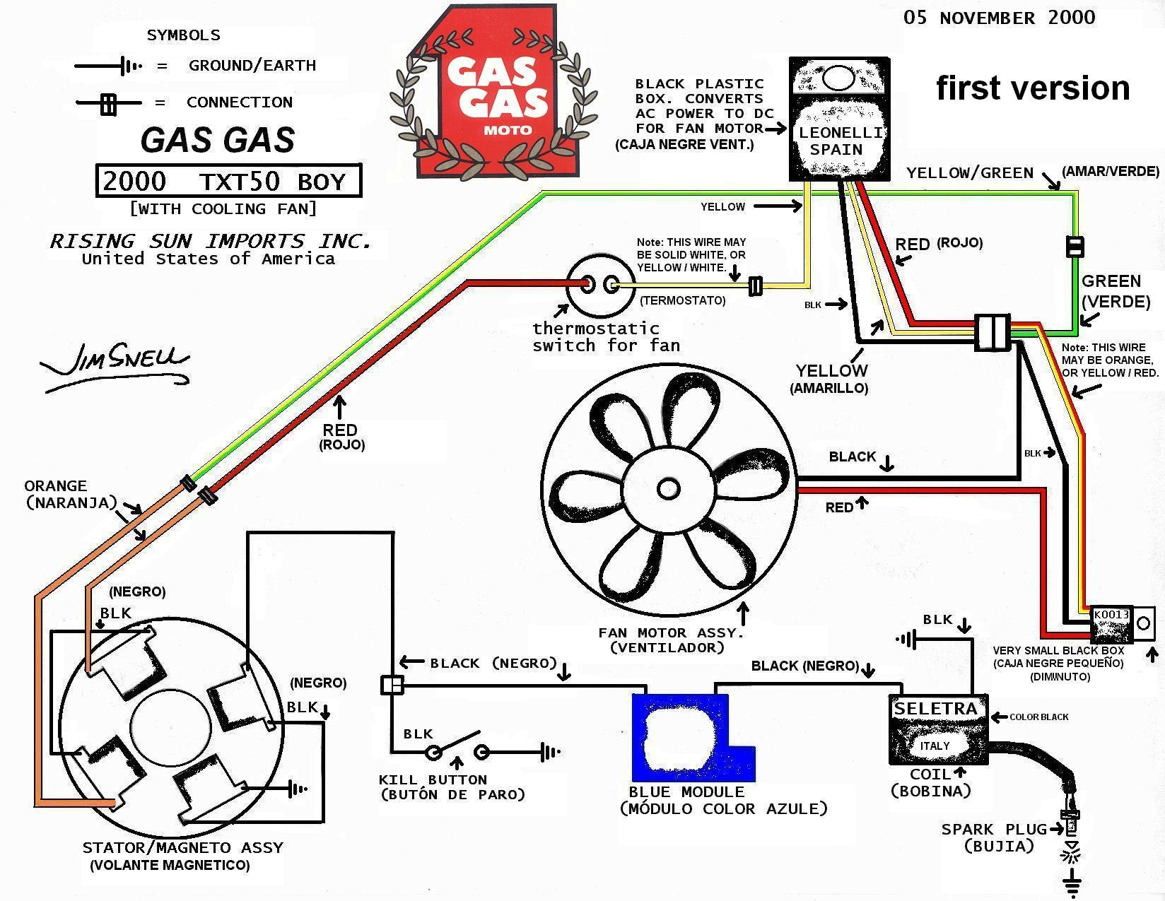
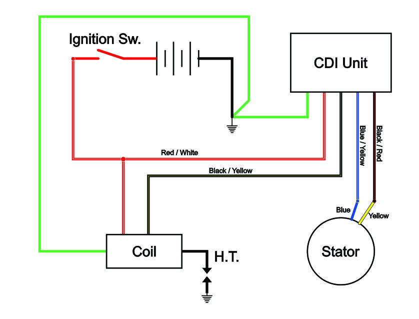
The racing CDI TZR 50 wiring diagram contains a multitude of components, each with its own purpose and connection. These components include the CDI unit itself, the ignition coil, the stator, the ignition switch, the kill switch, and more.
5 Pin Cdi Box Wiring Diagram For Your Needs
Use the wiring diagram below as a template. Reconnect the Negative battery cable. CYLINDER INSTALLATION Disconnect the Negative battery cable. Loosen the mounting plate for the Ignition coils and the Switchboxes. Disconnect the old Switchbox wires and remove the Switchbox from the mounting plate. Save the original mounting bolts.
5 Pin Cdi Wiring Diagram Wiring Harness Diagram
Try EdrawMax and make 5 Pin CDI Wiring Diagram easily https://bit.ly/3BJWfFz Explore Wiring Diagrams, and free use and edit 5000+ diagram examples here http.

Chinese 5 Pin Cdi Wiring Diagram
About Press Copyright Contact us Creators Advertise Developers Terms Privacy Policy & Safety How YouTube works Test new features NFL Sunday Ticket Press Copyright.
